 Products & ServicesExperienceWho We AreContact UsRequest More Information
Corvette Restoration Parts Tech Article
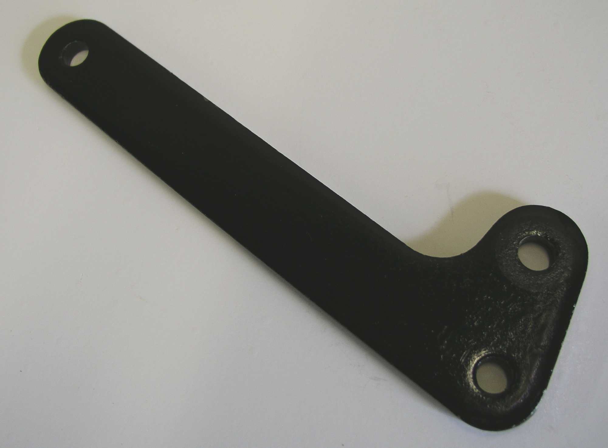
Background: Emergency brake is hard to operate and ineffective in stopping or holding card on a hill. On most 64 - 66 before 1 April 66 had parking brake lever PN: 3842938 as per assembly manual. This lever did not allow user to apply adequate force to the Emergency operating cable with a reasonable force on the Emergency Brake pull handle. Technical Service Bulletin TSB #66-59, HIGH PARKING BRAKE APPLICATION - was issued on May 4, 1966 to instruct dealers to modify the emergency brake braket and install a new lever. The Emergency Brake is a pull handle under the dash, attached to the frame mounted lever via a cable, the cable, pulley and bracket are mounted to the outside of the fire wall and direct the cable downward, to the lever arm and then a pull rod with cable holder and two self locking adjusting nuts. This pulls the emergency brake cable that attaches to both rear brake shoes. A large return spring is used to pull the lever to its retracted position. After 01 April 66 the lever used in production was changed and was assigned PN:3899399. This new design changed the linkage ratio from 4.800 to 5.714, increasing the force applied to the rear emergency brake cable. Assuming a 30 lb pull on the brake handle the brake application force increased to 173 lb from 144lb. The levers are very similar, the long dimension is the same, the short dimension was rt dimension was reduced, the overal shape is the same, no PN was stamped on them, and they can be identified only by the dimensions. The major hole to hole dimension is 6.00 " in all cases. The 1st design had a secondary hole center to center of 1.250". The second design had a secondary hole center to center of 1.020" TheService Bulletin shows the lever arm bracket modification that is necessary to clear the pull rod / lever connection with the new ratio. PN 3842938. (1st Design) Fig. 1: 64 to E66 Lever PN:3842938 PN 3899399. (2nd Design)
Fig. 2: L66 Lever PN: 3899399 Frame Modification from late 66 Frame.
Fig3: Mounting Bracket Modification Fractory frame mounting bracket modification occurred before the new lever arm was available for production. Several earlier 66 cars with lower SN (16,nnn) numbers were checked and they had the notch in the emergency brake bracket but had the 1st design lever. The bracket notch is 3/8 X 5/8 with a 1/ 8 in radius. See Fig 3: Why should you care: 1.0 From a practical point of view it is nice to know that if needed your emergency brake will work. 2.0 If you are going for a PV (performance verification) then you do care because the 1st design lever will make it difficult for you to pass the Emergency Brake functionality test. Common Problems: 1. There are other reasons the Emergency Brake effort is very high. If cars have been rebuilt the bolt mounting the pulley on the firewall may not be a shoulder bolt and the bronze bushing may not be lubricated. Disassemble clean and lubricate - replace bolt and pulley if necessary. 2. The cable is attached to the lever with a cable bracket / clevis pin / cotter key. Clean and make sure the clevis is frnd make sure the clevis is free to move. Lubricate with a high temperature grease. 3. The lever is mounted on the bottom of the frame braket under the car with the bolt facing downward, shoulder spacer facing upward (threw the frame bracket) and locking nut. When cars are rebuilt the spacer is often lost. Clean and lubricate> the spacer / lever and if necessary replace corroded fasteners. 4. The pull rod is mounted to the lever with a washer / spring J clip. Clean and lubricate the pull rod and make sure that there is not excessive ware on the lever or pull rod. 5. The rear emergency brake cable is mounted with a U shaped U bracket that holds the cable captive and allows you to adjust the free play in the emergency brake system. Make sure that new nuts are used and the spring is present to control cable tension and release of the brake. Replace Lever with 2nd Design: Replacing the 1st design lever with the 2nd design requires that a clearance notch be cut into the frame mounting bracket. The service bulitin describes this modification. You can use a small hack saw, or die grinder with a burr to make the notch in the braket. After you are satisfied that adequate clearance for the pued that adequate clearance for the pull rod end is available mount the lever to the frame bracket. It is time to clean and paint the modified frame bracket. Assemble as in the service manual, and make final adjustments. Adjustments: 1. Adjust the emergency brake shoes according to the Chevrolet Service Manual . 2. Adjust the cable / pull rod to allow some free travel and not be trying to apply the emergency brake. Burnish new parking brake shoes: Apply the emergency brake lightly and drive the car for a few hundred feet to make sure the new parking brake shoes are seated. This was done at the factory by pulling the car off the production line with the Emergency Brakes applied and driving to the parking / shipping lot. (Courtesy of Delco Products Brake Engineer Ret.) Test: Never test this on the open road by> Never test this on the open road by pulling the emergency brake at 50 mph. These are mechanical brakes and may cause the car to veer off course. At this point if all is proper your emergency brake should operated properly. A complete kit that includes a copy of the service bullitin, instructions on how to modify the frame bracket, a new lever, bolt / nut set, shoulder washer, cotter pin, and Curley J clip is available from Volunteer Products. PN 30-00164A02 for the Lever only PN 30-00164K01 for the complet Kit . Volunteer Vette Products PN: BRO42E |


Copyright © 2006 MicroControls. All Rights Reserved.